Quantcast
Channel: Parts of a Mobile Phone – Mobile Phone Repairing
Viewing all 22 articles
Browse latest View live

Card Level Parts of a Mobile Cell Phone

$
0
0

When learning how to repair a mobile cell phone, it is important to identify parts of a mobile phone. There are hundreds of parts and electronic components in mobile phone. These parts and components can be classified into different groups such as card level parts, big parts and small parts. In this article, I will explain and teach you about card level parts of a mobile phone. Big parts and small parts and electronic components will be covered in future articles.


// ]]>

Card Level Parts of a Mobile Cell Phone

  1. Front Facia or Facial: This is the front cover or housing of any mobile phone. These are of different shapes and sizes depending upon brand and model.

    Mobile Phone Front Facia

    Mobile Phone Front Facia

  2. Back Facia or Facial: This is the Back cover or housing of any mobile phone. These are of different shapes and sizes depending upon brand and model.

    Mobile Phone Back Facia

    Mobile Phone Back Facia

  3. Internal Facia or Facial: This is the internal skeleton of a mobile phone.

    Internal Facia or Skeleton of a Mobile Phone

    Internal Facia or Skeleton of a Mobile Phone

  4. Ringer: This part of component in a mobile phone is also called loudspeaker. It plays loud sound and music in mobile phone.

    Mobile Phone Ringer

    Mobile Phone Ringer

  5. Speaker: This part or component is also called earpiece. It helps to listen to sound during phone call when the loudspeaker or headphone is NOT ON.

    Mobile Phone Speaker

    Mobile Phone Speaker

  6. Microphone: It is also called Mic in short. It transmits sound of the speaker during phone call. It also helps to record sound in a mobile phone. It other words, microphone is a sound input device.

    Mobile Phone Microphone

    Mobile Phone Microphone

  7. Vibrator: It is also called motor. It creates vibration in a cell phone when vibration mode setting is turned ON.

    Vibrator of Mobile Phone

    Vibrator of Mobile Phone

  8. LED: Light Emitting Diode. These components produce light in a mobile cell phone.

    LED of Mobile Phone

    LED of Mobile Phone

  9. Charging Connector: It helps to connect the charger to the PCB of a mobile phone to charge or recharge the battery.

    Mobile Phone Charging Connector

    Mobile Phone Charging Connector

  10. Headphone Connector: It is also called Earphone Connector. It helps to connect the headphone to the mobile phone via jack.

    Mobile Phone Headphone Connector

    Mobile Phone Headphone Connector

  11. Data Cable Connector: It helps to connect the mobile to another device such as a computer, laptop, table etc using a data cable.

    Data Cable Connector of Mobile Phone

    Data Cable Connector of Mobile Phone

  12. Battery: It supplies power or DC current to the mobile phone.

    Battery of Mobile Phone

    Battery of Mobile Phone

  13. Battery Connector: It connects the battery to the internal circuit tracks of the PCB of a mobile phone.

    Mobile Phone Battery Connector

    Mobile Phone Battery Connector

  14. SIM Card: Subscriber Identification Module. This is a small rectangular chip with circuit and information of user of the card. A SIM card is necessary to make or receive phone calls with a mobile phone.

    SIM Card

    SIM Card

  15. SIM Card Connector: It connects the SIM card to the Circuit or PCB of a mobile phone.

    SIM Connector

    SIM Connector

  16. Memory Card: It is used to store data like document, music, videos etc. These are available in different capacities like 1GB, 2GB, 4GB, 8GB, 16GB, 32 GB etc.

    Memory Card

    Memory Card

  17. Memory Card Connector or MMC Connector: It connects the memory card to the PCB of a mobile phone.

    Mobile Phone Memory Card Connector

    Mobile Phone Memory Card Connector

  18. Camera: It is used to capture still images or record videos. These are available in different megapixel.

    Camera of Mobile Phone

    Camera of Mobile Phone

  19. Camera Connector: It connects the camera to the PCB of the mobile phone.

    Mobile Phone Camera Connector

    Mobile Phone Camera Connector

  20. Keypad Button: It is connected to the keypad carbon to enter numbers to make phone calls and other data.

    Mobile Phone Keypad

    Mobile Phone Keypad

  21. Keypad Carbon: It is present in between keypad button and the PCB. It connects the keypad buttons to the PCB of a mobile phone.

    Mobile Phone Keypad Carbon

    Mobile Phone Keypad Carbon

  22. Keypad Connector: It connects the keypad to the PCB of the cell phone.

    Mobile Phone Keypad Connector

    Mobile Phone Keypad Connector

  23. ON / OFF Switch: It helps to switch the mobile phone ON or OFF.
  24. Display: It is screen of the mobile phone.

    Mobile Phone ON-OFF Switch

    Mobile Phone ON-OFF Switch

  25. Display Connector: It connects display of screen to the PCB of a Mobile Phone.

    Mobile Phone Display Connector

    Mobile Phone Display Connector

  26. Internal Antenna: It helps to capture network frequency.

    Internal Antenna of Mobile Phone

    Internal Antenna of Mobile Phone

  27. PCB: Printed Circuit Boardof the Mobile Phone.

    Mobile Phone PCB

    Mobile Phone PCB

  28. PDA: Display or Screen of a touch screen mobile phone.

    Mobile Phone PDA

    Mobile Phone PDA


// ]]>
Related Articles:


Mobile Phone Parts Identification | How to Identify Parts & Components on PCB of Mobile Phone

$
0
0

When learning how to repair a mobile cell phone, it is important to learn how to identify parts and components on the PCB of a mobile cell phone. Identification of these parts and components is not that difficult.

The PCB of any mobile phone of any brand namely Nokia, Samsung, Motorola, China Mobile Phones etc is divided into 2 Parts namely: (1) Network Section; and (2) Power Section. When identifying parts, electronic components and ICs on the PCB of a mobile cell phone, it is important to keep these two sections in mind.

// ]]>
How to Identify Parts and Components on the PCB of a Mobile Cell Phone:

  1. Antenna Point: The point where antenna is connected is called antenna point. It is normally located at the top of the PCB of a mobile phone.

Network Section: The section below antenna point and above power section is called network section.

  1. Antenna Switch: It is found in the network section. It is made from metal and non-metal. It has 16 points or legs. In some mobile phones, the antenna switch is merged with PFO.

    Antenna Switch of Mobile Phone

    Antenna Switch of Mobile Phone

  2. PFO: Power Frequency Oscillator. It is present beside the antenna switch.

    PFO of a Mobile Phone

    PFO of a Mobile Phone

  3. Network IC: It is below or beside the antenna switch and PFO. In some mobile phones, the Network IC is merged with the CPU. E.g.: Nokia 1200, 1650, 1208, 1209 etc.

    Network IC of a Mobile Phone

    Network IC of a Mobile Phone

Power Section: This section is below the Network Section.

  1. Power IC: In the Power Section, the IC around which there are several brown-colored capacitors is called Power IC. In some mobile phones there are 2 Power ICs.

    Power IC of a Mobile Phone

    Power IC of a Mobile Phone

  2. CPU: Central Processing Unit. In the power section, the largest IC is the CPU. In some sets there are 2 CPU.

    CPU of a Mobile Phone

    CPU of a Mobile Phone

  3. Flash IC: This IC is found beside the CPU.

    Flash IC of a Mobile Phone

    Flash IC of a Mobile Phone

  4. Logic IC: The IC with 20 legs is the Logic IC.

    Logic IC of a Mobile Phone

    Logic IC of a Mobile Phone

  5. Charging IC: In the Power Section, the IC beside R22 is the Charging IC.

    Charging IC of a Mobile Phone

    Charging IC of a Mobile Phone

  6. Audio IC: The IC parallel to Power IC is the Audio IC.

    Audio IC of a Mobile Phone

    Audio IC of a Mobile Phone

NOTES:

  1. UEM (Universal Energy Manager) = Logic IC + Charging IC + Audio IC + Power IC
  2. PFO (Power Frequency Oscillator) = Antenna Switch + PFO
  3. Flash IC= RAM + Flash IC

    Mobile Phone PCB Layout Diagram

    Mobile Phone PCB Layout Diagram


// ]]>
Related Posts:

Parts of a Mobile Cell Phone and Their Function (Big Parts)

$
0
0

There are all kinds of parts and electronic components in a mobile cell phone. These parts and components can be divided into Big Parts and Small Parts. This article explains all about big parts and components in a mobile cell phone and their function.

When learning how to repair a mobile cell phone, it is important to identify its parts and understand their function. Here I must also remind you that any PCB of a mobile phone is divided into 2 sections namely: Network Section; and Power Section. Have a look at the image below to understand PCB of a mobile cell phone.

Mobile Phone PCB Diagram with Parts

Mobile Phone PCB Diagram with Parts


// ]]>
Big Parts of a Mobile Cell Phone and Their Function:

  1. Antenna Switch: It is found in the Network Section of a mobile phone
    Cell Phone Antenna Switch

    Cell Phone Antenna Switch

    and is made up of metal and non-metal. In GSM sets it is found in white color and in CDMA sets it is found in golden metal.

    Work: It searches network and passes forward after tuning.

    Faults: If the Antenna Switch is faulty then there will be no network in the mobile phone.

  2. P.F.O: It is found near the Antenna Switch in the Network Section of the
    Cell Phone PFO

    Cell Phone PFO

    PCB of Mobile Phone. It is also called P.A (Power Amplifier) and Band Pass Filter.

    Work: It filters and amplifies network frequency and selects the home network.

    Faults: If the PFO is faulty then there will be no network in the mobile phone. If it gets short then the mobile phone will get dead.

  3. RF IC / Hagar / Network IC: This electronic component found near
    Cell Phone Network IC / RF IC

    Cell Phone Network IC / RF IC

    the PFO in the Network Section of a Mobile Phone. It is also called RF signal processor.

    Work: It works as transmitter and receiver of audio and radio waves according to the instruction from the CPU.

    Faults: If the RF IC is faulty then there will be problem with network in the mobile phone. Sometimes the mobile phone can even get dead.

  4. 26 MHz Crystal Oscillator: It is found near the PFO in the Network
    Mobile Phone 26 MHz Crystal Oscillator

    Mobile Phone 26 MHz Crystal Oscillator

    Section of a Mobile Phone. It is also called Network Crystal. It is made up of metal.

    Work: It creates frequency during outgoing calls.

    Faults: If this crystal is faulty then there will be no outgoing call and no network in the mobile phone.

  5. VCO: It is found near the Network IC in the Network Section of a Mobile
    Mobile Phone VCO

    Mobile Phone VCO

    Phone.

    Work: It sends time, date and voltage to the RF IC / Hager and the CPU. It also creates frequency after taking command from the CPU.

    Faults: If it is faulty then there will be no network in the mobile phone and it will display “Call End” or “Call Failed”.

  1. RX Filter: It is found in the Network Section of a Mobile Phone.
    Mobile Phone RX Filter

    Mobile Phone RX Filter

    Work: It filters frequency during incoming calls.

    Faults: If it is faulty then there will network problem during incoming calls.

  1. TX Filter: It is found in the Network Section of a Mobile Phone.
    Mobile Phone TX Filter

    Mobile Phone TX Filter

    Work: It filters frequency during outgoing calls.

    Faults: If it is faulty then there will network problem during outgoing calls.

  1. ROM: It is found in the Power Section of a Mobile Phone.
    Mobile Phone ROM

    Mobile Phone ROM

    Work: It loads current operating program in a Mobile Phone.

    Faults: If ROM is faulty then there will software problem in the mobile phone and the set will get dead.

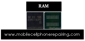
  1. RAM: It is found in the Power Section of a Mobile Phone.
    Mobile Phone RAM

    Mobile Phone RAM

    Work: It sends and receives commands of the operating program in a mobile phone.

    Faults: If RAM is faulty then there will be software problem in the mobile phone and it will get frequently get hanged and the set can even get dead.

  1. Flash IC: It is found in the Power Section of a Mobile Phone. It is also
    Cell Phone Flash IC

    Cell Phone Flash IC

    called EEPROM IC, Memory IC, RAM IC and ROM IC.

    Work: Software of the mobile phone is installed in the Flash IC.

    Faults: If Flash IC is faulty then the mobile phone will not work properly and it can even get dead.

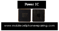
  1. Power IC: It is found in the Power Section of a Mobile Phone. There are
    Cell Phone Power IC

    Cell Phone Power IC

    many small components mainly capacitor around this IC. RTC is near the Power IC.

    Work: It takes power from the battery and supplies to all other parts of a mobile phone.

    Faults: If Power IC is faulty then the set will get dead.

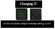
  1. Charging IC: It is found in the Power Section near R22.
    Cell Phone Charging IC

    Cell Phone Charging IC

    Work: It takes current from the charger and charges the battery.

    Faults: If Charging IC is faulty then the set will not get charged. If the Charging IC is short then the set will get dead.

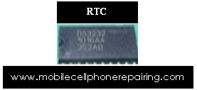
  1. RTC (Simple Silicon Crystal): It is Real Time Clock and is found in
    Mobile Phone RTC (Real Time Clock)

    Mobile Phone RTC (Real Time Clock)

    the Power Section near Power IC. It is made up of either metal or non-metal. It is of long shape.

    Work: It helps to run the date and time in a mobile phone.

    Faults: If RTC is faulty then there will be no date or time in the mobile phone and the set can even get dead.

  1. CPU: It is found in the Power Section. It is also called MAD IC, RAP IC
    Cell Phone CPU

    Cell Phone CPU

    and UPP. It is the largest IC on the PCB of a Mobile Phone and it looks different from all other ICs.

    Work: It controls all sections of a mobile phone.

    Faults: If CPU is faulty then the mobile phone will get dead.

  1. Logic IC / UI IC: It is found in any section of a mobile phone. It has 20
    Cell Phone Logic IC

    Cell Phone Logic IC

    pins or legs. It is also called UI IC and Interface IC.

    Work: It controls Ringer, Vibrator and LED of a mobile phone.

    Faults: If Logic IC / UI IC is faulty then Ringer, Vibrator and LED of mobile phone will nor work properly.

  1. Audio IC: It is found in Power Section of a mobile phone. It is also
    Cell Phone Audio IC

    Cell Phone Audio IC

    called Cobba IC and Melody IC.

    Work: It controls Speaker and Microphone of a mobile phone.

    Faults: If Audio IC is faulty then Speaker and Microphone of a mobile phone will not work and the set can even get dead.


// ]]>
Related Posts:

Small Parts / Electronic Components of Mobile Phone and Their Function

$
0
0

The PCB of a mobile cell phone has several small parts or electronic components. When learning mobile repairing, it is important to learn and understand how to identity these small parts or electronic components and understand their function. Identification of these small parts on the PCB of a mobile phone is easy if you know and understand some of the basic rules. It is also important to understand what to do if any of these small components is faulty.

Most of these electronic components are SMD (Surface Mount Devices). They don’t have any leads like thru-hole electronic components.


// ]]>

Small Parts / Electronic Components of a Mobile Phone: Identification, Faults and Function:

Boost Coil: Its size is little bigger than coil. It is found in black colour and

Mobile Phone Coil

Mobile Phone Coil

looks like a large button. Its function is to increase current. If this coil gets damaged then it has to be changed.

Coil: It is found in any section of a mobile phone. It is found in many shapes and sizes. Coils are found in 2 colours: (i) Black and white; and (ii) Blue and white. It has binding of copper coil inside. It filters and decreases Current and Voltage.

Capacitor: 3 types of capacitor are found in a mobile cell phone:

  1. Non-Electrolytic Capacitor: It is found in any section of a mobile
    Mobile Cell Phone Capacitor

    Mobile Cell Phone Capacitor

    phone. Its height is little more than chip resistance. It can be of gray, yellow or brown in color. It has no Positive (+) or Negative (-) side. It filters DC current.

  1. Electrolytic Capacitor: It is found in any section of a mobile phone. Its size is larger than non-electrolytic capacitor. It is found in 2 colors – (i) Orange with brown strip: and (ii) Black with white strip. The side with the strip is Positive (+) and the other side is Negative (-). It filters and stores current.
  1. Network Capacitor: It is found in any section of a mobile phone. It is made from 2 or more Non-Electrolytic Capacitors.

Coupler: This electronic component is found in the Network Section of a

Mobile Phone Coupler

Mobile Phone Coupler

mobile phone. It is of either black or white color and has 6 pins bent inside.

Function: It filters network.

Faults: If the coupler is faulty then there will be no network in the mobile phone.

Diode: Diodes are of 4 types:-

  1. Rectifier Diode: It is found in black color and converts AC Current to DC Current. It passes current in one direction. It does not pass current in reverse direction.

    Mobile Phone Rectifier Diode

    Mobile Phone Rectifier Diode

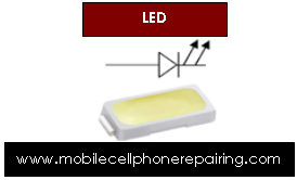
  1. LED: It is found in white or light yellow color and emits light.

    Mobile Phone LED

    Mobile Phone LED

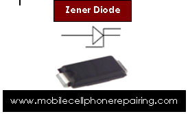
  1. Zener Diode: It is found in charging section. It filters and minimize current and passes forward. It acts as voltage regulator. Zener diode has fixed capacity like 4V, 6V, 8V etc.

    Mobile Phone Zener Diode

    Mobile Phone Zener Diode

  1. Photo Diode: It is used for Infrared. It captures Infrared Rays.

    Mobile Phone Photo Diode

    Mobile Phone Photo Diode

Regulator: This electronic component is found in any section of a mobile phone. It is of black color and has 5 or 6 legs. It filters current and regulates voltage.

Mobile Phone Regulator

Mobile Phone Regulator

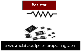
Resistance or Resistor: There are 2 types of resistance on the PCB of a

Mobile Phone Resistor

Mobile Phone Resistor

mobile phone:

  1. Chip Resistance: It can be found in any section of a mobile phone. It is of black color. In some sets it is also found in blue and green colour. It is the smallest electronic components on the PCB of a mobile phone. It Decreases current and passes forward.
  1. Network Resistance: It can be found in any section of a mobile phone. It is made from 2 or more Chip Resistance.

Transistor: This electronic component is found in any section of a mobile phone. It is of black color and it has 3 legs. It does the work of switching.

Mobile Cell Phone Transistor

Mobile Cell Phone Transistor


// ]]>

Related Posts:

Counting Legs or Pins of IC

$
0
0

Any mobile phone PCB has several IC or Integrated Circuit. These are SMD or Surface Mount Electronic Components. Before understanding how to count legs or pins of any IC, let us learn about IC.

What is an IC?

An IC is an electronic component made up of combination or integration of several other electronic components like resistor, capacitor, coil, diode, transistor etc.

How Many Types of IC are There?

There are mainly 2 types of ICs:

  1. Leg-Type IC: This type of IC has legs or pins. These types of ICs are again divided into different categories but we will not discuss it here because it has nothing to do with mobile repairing.
  2. Ball-Type IC: This type of IC has BGA (Ball Grid Array) underneath the IC. These types of ICs are again divided into different categories but we will not discuss it here because it has nothing to do with mobile repairing.


// ]]>

How to Count Legs or Pins of Leg-Type IC?

Counting of leg-type IC starts in Numerical Digit in Anticlockwise Direction starting from the Nose Point or Cut Point. Have a look at the photo below to understand it clearly.

How to Count Legs or Pins of Leg-Type IC

How to Count Legs or Pins of Leg-Type IC

How to Count Balls of Ball-Type IC?

Counting of Ball-type IC is done in Both Clockwise and Anti-Clockwise Direction. Rows are counted in Digit Numbers (1, 2, 3, 4…) in Clockwise Direction. Columns are counted in Alphabet (A, B, C, D…) in Anti-Clockwise Direction.

NOTE: When counting Columns, “I” and “O” are omitted because they look like “1” and “0”.

How to Count Balls of Ball-Type IC

How to Count Balls of Ball-Type IC


// ]]>

Related Posts:

Circuit Symbol / Circuit Schematic Symbols of Electronic Components

$
0
0

What are Circuit Symbols and why are these Schematic Symbols Used?

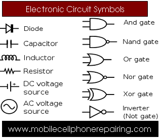
Circuit symbols are symbols, signs or pictogram of electronic components to represent electrical and electronic components and devices schematic diagram of an electronic circuit. Even though these symbols can be different in different countries, there are some common standards set by IEC and ANSI to represent electronic components.

These electronic circuit symbols are used in circuit diagrams to explain how a circuit is interconnected.

NOTE: The original layout of electronic components is different from the circuit diagram. To build an actual electronic circuit we need different diagram showing the layout of the parts on printed circuit board.


// ]]>

Below are circuit symbols of most common electronic components:

  • AC Current Circuit Symbol

    AC Current Circuit Symbol

    AC Current Circuit Symbol

  • DC Current Circuit Symbol

    AC Current Circuit Symbol

    DC Current Circuit Symbol

  • Capacitor Circuit Symbol

    Capacitor Circuit Symbol

    Capacitor Circuit Symbol

  • Coil Circuit Symbol

    Coil Circuit Symbol

    Coil Circuit Symbol

  • Crystal Circuit Symbol

    Crystal Circuit Symbol

    Crystal Circuit Symbol

  • Resistor Circuit Symbol

    Resistor Circuit Symbol

    Resistor Circuit Symbol

  • Diode Circuit Symbol

    Diode Circuit Symbol

    Diode Circuit Symbol

  • LED Circuit Symbol

    LED Circuit Symbol

    LED Circuit Symbol

  • Transistor Circuit Symbol

    Transistor Circuit Symbol

    Transistor Circuit Symbol

  • Fuse Circuit Symbol

    Fuse Circuit Symbol

    Fuse Circuit Symbol

  • Regulator Circuit Symbol

    Regulator Circuit Symbol

    Regulator Circuit Symbol

Other Electronic Components Symbols

Circuit Symbols of Electronic Components

Circuit Symbols of Electronic Components

Circuit Symbol of Resistor - American-style resistor (a), rheostat (variable resistor) (b), and potentiometer (c), IEC-style resistor

Circuit Symbol of Resistor – American-style resistor (a), rheostat (variable resistor) (b), and potentiometer (c), IEC-style resistor

Circuit Symbol of Capacitor - Capacitor, Capacitor, polarized, Capacitor, variable

Circuit Symbol of Capacitor – Capacitor, Capacitor, polarized; Capacitor, variable

Circuit Symbol of Transistor - NPN transistor, PNP transistor, n-channel junction gate field-effect transistor (JFET), p-channel junction gate field-effect transistor (JFET), Field-effect transistor

Circuit Symbol of Transistor – NPN transistor, PNP transistor, n-channel junction gate field-effect transistor (JFET), p-channel junction gate field-effect transistor (JFET), Field-effect transistor

Circuit Symbol of Diode - Diode, Zener diode, Tunnel diode, Schottky diode, Light Emitting Diode (LED), Photodiode, Varicap

Circuit Symbol of Diode – Diode, Zener diode, Tunnel diode, Schottky diode, Light Emitting Diode (LED), Photodiode, Varicap

Circuit Symbol of Vacuum Tube - Vacuum tube diode, Vacuum tube triode, Vacuum tube tetrode, Vacuum tube pentode

Circuit Symbol of Vacuum Tube – Vacuum tube diode, Vacuum tube triode, Vacuum tube tetrode, Vacuum tube pentode

Circuit Symbol of Switch - Switch, Single Pole/Single Throw (SPST), Switch, Single Pole/Double Throw (SPDT), Switch, Double Pole/Double Throw (DPDT)

Circuit Symbol of Switch – Switch, Single Pole/Single Throw (SPST), Switch, Single Pole/Double Throw (SPDT), Switch, Double Pole/Double Throw (DPDT)

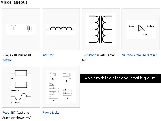
Circuit Symbols - Single cell, multi-cell battery, Inductor, Transformer with center tap, Silicon-controlled rectifier, Fuse, Phone jack

Circuit Symbols – Single cell, multi-cell battery, Inductor, Transformer with center tap, Silicon-controlled rectifier, Fuse, Phone jack

// ]]>
Related Posts:

Sections and Parts Inside a Mobile Cell Phone

$
0
0

Any mobile cell phone including – Samsung, Nokia, LG, Motorola, Sony Ericsson, Acer, Alcatel, Apple, Amoi, Asus, BenQ, Siemens, Bird, Blackberry, Blu, Celkon, Dell, Gigabyte, Haier, HTC, Huawai, Micromax, Panasonic, Philips, Sagem, Spice, Toshiba, ZTE Etc have different parts or sections inside the mobile cell phone. These parts can be divided into following different sections:

Parts Inside a Mobile Cell Phone

Parts Inside a Mobile Cell Phone

// ]]>

  1. Keyboard or Keypad Section: The keyboard section of any mobile cell phone is directly connected with the CPU. This means that rows and columns of keys are directly connected with the CPU. Protector IC or Interface IC or Verector diode is connected in the row or column line for the protection of key section. In modern mobile cell phones which have qwerty keys, a separate control IC is connected with the CPU for extra protection to the keys.
  2. Display Section: The display section is directly connected with the CPU to receive following signals – LCD Data Signal, LCD Reset Signal, LCD WR Signal, LCD RD Signal, LCD FLM Signal, LCD HSYN Signal etc. These signals are given to the LCD Module through the CPU. 2.8V power supply or 1.8V power supply is given to the LCD for functioning. LCD signal interface filter are connected in many mobile cell phones for interfacing these signals of LCD Module.
  3. SIM Card Section: The SIM Card Interface section is directly connected with the CPU in most mobile cell phones. If there is no power supply in a mobile phone then the SIM section is connected with the CPU through the Power IC. Mainly V-SIM (3.0V), SIM-RST (2.85V), SIM CLK, SIM-Data (2.5V), and SIM GND are made in the SIM Section. These four pins (Beside (SIM GND) are directly connected with the SIM interface / control section and V-SIM volt are given to the SIM data pin from V-SIM pin through the 10-18 Kilo Ohms Resistance.
  4. Memory Card Section: Now mostly Micro SC Card is connected in most mobile cell phones which is connected with micro card section through a 8 pin socket. Memory card section is made inside the CPU. Description of these 8 pins are as follows:
    1. MMC-Data-2
    2. MMC Data
    3. MMC CMD (Command)
    4. VMMC / VSD (Positive Supply Pin)
    5. MMC-CLK
    6. GND
    7. MMC-Dta0
    8. MMC Data-1

    2.8 Volt Power is supplied to Pin Number 4 from Power Supply for functioning of the MMC Card and connection the 50 tp 100 Kilo Ohms resistance in this power supply. This power supply is given to Pin Numbers – 1,2,3,7,8 of MMC Socket. One MMC detector switch or pin is made in MMC socket at which, if there is no MMC Card then 1.8 V power is continuously received and after the MMC is connected, it becomes zero.

  5. MIC Interface Section: MIC interface section is directly connected with the CPU inmost mobile phones. Working voltage (MIC Bios) (1.8 to 2.8 V) is supplied from the CPU or the Power Supply Section for functioning of the MIC and MIC Positive and Negative Volt are input through two capacitors.
  6. Ear Speaker Section: In most modern mobile cell phones, in which there is a separate ear speaker, it is directly to the CPU. It receives sound via signals directly from the CPU of from the audio section inbuilt within the CPU. In some mobile phones, these sound signals are received via coil / resistance. Some mobile phones have audio IC in the audio section. Some mobile phones have audio amplifier.
  7. Speaker / Ringer Section: Ringer, Buzzer or Speaker in most mobile phones are connected with the audio amplifier IC to obtain loud sound. The amplifier IC amplifies the sound or audio signal received from the CPU of the audio section.
  8. Key Backlight Section: LED Lights are connected according to the parallel circuit in the key backlight section. Anode ends of all the LEDS are connected to each other and all the cathode ends are to each other. 3 to 3.3 V is supplied for the functioning of these Key LED Lights. This power supply is given to the cathode ends of LEDs from the ground ends. Power supply to the anode ends of LED Lights is controlled bu using LED-Driver or PNR IC.
  9. LCD Backlight Section: LCD Backlight in mobile cell phones is made according to the series circuit. A Boost Voltage Generator Section is built for the supply of high voltage (10 to 18V) for the functioning of the LCD LED. Boost coil, Boost Volt Driver IC, Rectifier Diode etc are present in this section.
  10. Vibrator Motor Section: Positive power supply is given to this section directly from the positive end of the battery. Negative power supply is given through a NPN transistor or from the ground of any circuit.
  11. Network Section: Antenna, External Antenna Socket, RX-Band Pass Filter, RF Crystal, FEM, PFO, TX-Band Pass Filter, RF IC, CPU are connected in the Network Section. Signal received at the antenna during the RX is given to the antenna switch or FEM through the antenna socket where the next processing is completed by selecting a frequency of proper band and is passed on to the RF IC through RX-Band Pass Filter. RF Signal out from the RF IC during TX is given to the FEM or PFO to amplify the signal. After the Band Selection Process the signal is passed through the antenna.
  12. Battery Charging Section: Charger and system interface connector is made together in most modern mobile cell phones. Regulator section is made separately for the battery charging section. In some mobile phones, the battery charging section is made inside the Power IC.
  13. FM Radio Section: FM Radio Driver IC, FM Antenna, Signal and Supply Components are made in the FM Radio Section.
  14. Bluetooth Section: Bluetooth Antenna, Bluetooth RF Signal Filter, Bluetooth Driver IC, Supply and Signal Components are made in this section. The Bluetooth sections functions like the Network Section. RF-CLK signal is given to the Bluetooth driver IC during signal processing.
  15. Set Power ON: Power IC, CPU (UCP), Flash IC, RF-CLK, Crystal, RF-IF, PWR Ket etc components are present this section. Battery positive supply is given to the power IC and connecting the battery (3.7V) from 2.87 to 3.0 Power ON Volts are received at one tip of the Power Key. Supply is given to the CPU, Flash IC, RF-CLK, Generator Section (RF Crystal, RF IC) by which the mobile phone gets switched ON.
  16. Handsfree (Earphone Section): Mainly hands free jack, hands free MIC, speaker signal component and hands free audio amplifier are present in this section. Hands free symbol is displayed after connection the Handsfree jack.

Related Posts:

// ]]>

  1. Top Mobile Cell Phone Manufacturers in the world – Best Leading Mobile Cell Phone Manufacturers

Mobile Phone Fault Finding for Mobile Cell Phone Repairing

$
0
0

In order to repair any mobile cell phone through circuit, we must know the section in which the fault is present and different parts and components present in that particular section. If we know different parts and components present in different sections inside a mobile cell phone then we can easily repair the fault by checking the component.

While doing mobile phone repairing, we can do fault finding if we know different sections inside a mobile cell phone. For Example – If there is Network Problem in a mobile phone then we can easily repair the phone if we know different parts, components and their function in the Network Section.

Mobile Phone Repairing

Mobile Phone Repairing


// ]]>

Following are different electronic parts and components in different sections inside a mobile cell phone:

  1. Network Fault: Antenna Switch, PFO, FEM, RF IC, VCO, RX-Filter, TX-Filter, RF Antenna, RF Crystal, External Antenna Socket, Network Signal and Supply Control and Interface Section. If we know about the parts and components present in the Network section and their function then we can easily repair the fault by looking at the code number of the faulty component in the Circuit Diagram and the PCB Layout Diagram. In this way we can easily make good use of circuit diagram for mobile cell phone repairing.
  2. Power ON Fault: Battery (3.7V), Battery Connector Jack, Power IC, CPU, Flash IC, S-RAM IC, RF Crystal, RF Clock Section Component, RF IC, Power ON / OFF Trigger Components.
  3. Charging Fault: Charger (5-6V), Battery (3.7V), Charger Connector, Charger Volt Fuse, Coil, Charger Over Volt Protector, Charging IC, Power IC, Charging Regulator, Charging Volt Output Components, Charger and Charger Volt Detector Components.
  4. SIM Fault: SIM Card, SIM Socket, SIM Signal and Supply Interface Components, Resistance, Coil, Power IC, CPU etc.
  5. Ringer Fault: Ringer, Ringer Signal Input and Output Components, Audio Amplifier IC, Power IC, CPU etc.
  6. Ear Speaker Fault: Ear Speaker, Ear Speaker Signal Components, Audio Amplifier IC, CPU, Power IC etc.
  7. Micro SD Card Fault / MMC Fault: Micro SD Card, Micro Card Connector, Micro Card Detector Switch, Micro Card Detector Signal Components, CPU etc.
  8. USB and Bottom Connector fault: USB and Bottom Connector, USB and Signal Interface Connector Components, USB Signal Interface IC, USB Driver IC, CPU etc.
  9. Keypad Fault: Key Tip, Key Pad Dot Sheet, Key Signal Filters, Key Signal Varactors, Key Board to Key Connector, CPU etc.
  10. Display Fault: LCD, LCD Connector, LCD Supply Components, LCD Signal Interface Filter IC, CPU, LCD Signal Interface Resistance etc.
  11. MIC Sound Fault: MIC, MIC Interface Connection, MIC Signal and Supply Components, Power IC, CPU etc.
  12. Backlight (LED) Fault: LED, Backlight Driver IC, Backlight Driver Section Components, Power IC, CPU etc.
  13. Bluetooth Fault: Bluetooth Antenna, Bluetooth Driver IC, Bluetooth Section Crystal, CPU etc.
  14. FM Radio Fault: Fands Free Lead, Hands Free Connector, FM and Bluetooth IC, FM Driver IC, CPU etc.
  15. Vibrator Fault: Vibrator Motor, Vibration Supply Components, Power IC, Vibrator Driver IC etc.
  16. Touch Panel (PDA) Fault: Touch Panel / PDA Panel, Touch Panel Control IC, CPU, Signal Interface Parts etc.

Related Posts:

// ]]>


Surface Mount Device (SMD) or Surface Mount Electronic Components

$
0
0

Circuit of a mobile phone looks like general circuit but the parts in printed circuit boards (PCB) of mobile phone are different from normal thru-hole electronic components. These electronic components are known as surface mount device or surface mount electronic components.

These SMD electronic components on the PCB of a mobile cell phone generally do not have any leads. Components that have leads are bent in a manner that they can be mounted only on the surface of the PCB and hence the name “Surface Mount Device”. Most of the electronic components on the PCB of a Mobile Cell Phone are BGA or Ball grid Array Packages.

SMD Components of Mobile Phone PCB

SMD Components of Mobile Phone PCB

What is SMD or Surface Mount Device or Surface Mount Electronic Component?

Surface mount devices of SMD are electronic components that are easily soldered or mountable on the surface on the PCB. Most of these PCBs are multilayered PCB which means these PCB have more than one layer. The technique of soldering or utilizing SMD components is called SMT (Surface Mount Technology).


// ]]>

What are Advantages of SMD?

SMD type electronic components offer many advantages. The main advantage is that they are space saving. The size of mobile phones has been significantly reduced because of the use of SMD components. SMD components use less electricity and voltage loss is also very less.

Uses of SMD Electronic Components?

Presently SMD of Surface Mount Devices are used in ultra modern electronic equipments like mobile cell phones, computers, laptops tablets etc. all the components used in Surface Mount Technology are mostly in the form of chips or IC (Integrated Circuit). These chips or ICs are classified into different categories depending of the type of legs or leads they have and their function. These components are mounted directly at the specified location on the copper track of the Printed Circuit Board using Surface Mount Soldering Technology.


// ]]>

Related Posts:

SMD Resistor – Surface Mount Chip Resistor Guide

$
0
0

SMD Resistor or Surface Mount Chip Resistor is an electronic component with the properties of both obstruction as well as resistance. The property of this component is called resistance.

What is Resistance?

The obstruction or resistance created by any matter in the flow of current is called resistance.

What is the Graphical Symbol of Resistor?

The Graphical Symbol of Resistor is :

Resistance Symbol

Resistance Symbol

Which Alphabetic Character Denotes a Resistor?

A resistor is denoted by the character: R

What Is The Work Of A Resistor?

The work of a resistor is to decrease current.

What is the Unit of Resistance?

The unit of resistance is: Ohm

What is the Power Rating of Resistor?

The power rating of resistor is Watt.

What does a SMD Resistor looks like?

A SMD resistor appears black from top with some blue colour. The colour at the bottom is white.

Points to Remember:

  • A resistor never gets short.
  • Resistor can be open.
  • Value of resistor can be high.
  • Resistor is available with or without code. Mostly resistors without code are used in mobile phones.
  • R and E alphabets in the resistor denote Ohms.
SMD Resistor

SMD Resistor


// ]]>


Different Types of SMD Resistors

  1. Network Resistor: Combination of more than one resistor groups is called network resistor. They are made in a single package.
  2. Chip Jumper (Zero Ohm) Type Resistor: This type of chip resistor is used as jumper in mobile phones.
  3. Thermistor-Type Resistor: The rating of this type of resistor depends on temperature. It is black in colour from all sides. These resistors are of two types – NTC Thermistor (Negative Temperature Co-efficient type Thermistor) and PTC Thermistor (Positive Temperature (Co-efficient type Thermistor).
  4. LDR (Light Dependent Resistor): This resistance is dependent upon light. Resistance of a LDR may be several mega Ohms in dark, but is reduced to few Ohms under light.

Coding of SMD Resistor

Generally a number equivalent to three band color code is written on a resistor. Like resistors of normal terminal, a 4 digit code is provided to denominate tolerance. First 2 or 3 digits denote the first two or three digits of values of the resistor and the third or last digit represents the numbers of zero. R is written before or after the value to denote the position of decibel point in the resistor below 10 Ohm value. Read the following examples:

  • Code : 330 = 33 Ohm
  • Code : 221 = 220 Ohm
  • Code : 683 = 68000 Ohm or 68 K Ohm
  • Code : 105 = 10,00000 Ohm or 1 M Ohm
  • Code : 8R2 = 8.2 Ohm
  • Code : 1000 = 100 Ohm
  • Code : 4992 = 49900 Ohm or 49.9 K Ohm
  • Code : 16234 = 162000 or 162 K Ohm

Tolerance or SMD Resistor

During manufacturing of resistors, some deficiency or excess may take place in its value. The tolerance of resistors used in mobile phones is almost zero.
How to Check a SMD Chip Resistor using a Multimeter

If the value of a resistor to be checked is 100 Ohm, then place probes of the Multimeter at both the soldering tips of the resistor and select knob of the Multimeter at 200 Ohm. Value of the resistor is displayed on the display screen of the Multimeter. If only 1 is displayed on the screen then it means that the resistor is OPEN and if the reading is too high then it means that the resistor is out of order or it is faulty. Resistors do not get shorted. Value of a resistor is considered OK within its tolerance limit.


// ]]>

Related Posts:

SMD Capacitor – Surface Mount Chip Capacitor Guide

$
0
0

SMD Capacitor or Surface Mount Chip Capacitor is an electronic component made up of an insulator between two conductors. This dielectric matter or insulator plays an important role of storing electric charge. There are several types of SMD capacitors. There are divided according to the dielectric matters used in their composition. Air, paper, mica and electrolyte capacitors are mostly used.

What is the work of SMD Capacitor?

The main function of any SMD capacitor is to store the electrical energy and re-supply i.e. charge and discharge electrical energy.

How is SMD Capacitor Made?

SMD capacitor is made up of metallic plates (good conductor of electricity). Both plates are separated using a bad conductor or dielectric.  The name of a capacitor is dependent on the dielectric matter used in the capacitor. If the electrolytic capacitor is yellow then its border are brown. If the capacitor is black then its border is silver.

SMD Capacitor

SMD Capacitor

What is the Graphical Symbol of Capacitor?

The Graphical Symbol of Capacitor is:

Capacitor Symbol

Capacitor Symbol

Which character or alphabet indicates a capacitor?

Capacitor is indicated by the alphabet C

What is the Work of a Capacitor?

The main function of a capacitor is to pass AC and stop DC.

What is the Unit of Capacitor?

The Unit of Capacitor is fared.

Ceramic SMD Capacitor

It is a type of capacitor in which ceramic is used as dielectric matter. These capacitors are rated according to the ceramic electrical properties. The electrical property of ceramic is multi dimensional.

Use of ceramic significantly reduces the size of SMD capacitor compared to other types of capacitors. Various ceramic dioxides are used in ceramic capacitors like barium titenate, barium strontium and titanium dioxide etc. Desired temperature coefficient is obtained by using various ceramic dielectric products. Di insulation is prepared by using multi layers of dielectric matters between two good conductors. This reduces the chance of its getting out or order. Its electrodes are generally plated with silver. This provides a high quality soldering property to the capacitor.


// ]]>

How to Check Electrolytic Capacitor?

If the value of the capacitor to be checked is 10 mF, then select 20 mF on the Multimeter. Connect the lead to the CX socket and place the probes on both sides of the soldering tips of the capacitor. If the display of the screen shows 10 then it means the capacitor is OK. If the screen shows 000 then it means the capacitor is open. If the screed displays 1 then the capacitor is short. The capacitor is considered OK if the value is within its tolerance level.

Please note that the above process is not applicable if the value of the capacitor to be checked is more than 20 mF. Knob of the selector switch should be selected according to the value of the capacitor.

How to Check Electrolytic Capacitor of Value higher than 20 mF?

Turn the selector know of the Multimeter on the symbol of Diode. Insert the probes turn by turn on Com and V / W / F Pins and keep checking the capacitor. If the reading increases and settles at 1 then it means the capacitor is OK. If the reading in both the cases remains 1 or the reading stops while ascending, it means the capacitor is out of order.

How to Check Simple Capacitor Using Multimeter?

If the reading on the Multimeter shows 000 after testing accompanied with a beep sound, it means the capacitor is short. If the reading shows 1, it means the capacitor might be open or even OK.


// ]]>

Related Posts:

SMD Coil – Surface Mount Chip Coil Guide

$
0
0

SMD Chip Coil is made by twisting any conductor wire on a bad conductor base. The base on which the coil is formed is called core. When these coils do not have any base, they are called air core coil. Coil is also known as conductor. A coil always resists any variation in flow of current. If any variable supply is given to any coil, the voltage of opposite polarity is generated in the coil. This property of a coil is known as inductance. Hence, a coil is also called inductor.

Types of SMD Coil or Inductor

There are many types of coil but surface mount coils are mostly used in mobile phones. These are tiny chip inductors directly soldered on the PCB track on the mobile cell phone. This type of inductor is called general purpose inductor. This is used for sharp frequency response for high quality factor. These inductors are made by spiraling wire on ferrite core with magnetic shield and surface mounting terminals are created on both ends after mounting it in a small hard package. These terminals are nickel coated for easy and better soldering on PCB Track. Nickel coating ensures reliable soldering.


// ]]>

What is the Graphical Symbol of Coil?

The Graphical Symbol of Coil is:

Coil Symbol

Coil Symbol

Which character or alphabet indicates a Coil?

Coil is indicated by the alphabet L

What is the Work of a Coil?

The main function of a Coil is to STOP AC and PASS DC.

What is the Unit of Coil?

SMD Coil

SMD Coil

The Unit of Coil is Hanery.

Effect of DC on Coil

A Coil passes DC Current like an ordinary wire. Magnetic properties are generated in the coil on getting DC. The power in the coil attracts iron particles.

Effect of AC on Coil

When AC current or Alternate Current or Variable Electric Current is given to a coil, a variable magnetic electric field is generated in the coil. AC voltage in opposite directions is generated due to this variable magnetic field which resists the AC volt.

How to Check Coil?

Place the selector knob of the Multimeter on Diode Sign. Now place the probes on both the terminals of the coil. If a beep sound is produced and the display reads close to 000, it means that the coil is OK. If the display shows 1, it means the coil is open.


// ]]>

Related Posts:

SMD Transformer – Surface Mount Chip Transformer Guide

$
0
0

A SMD Transformer is made from coils. There are a minimum of 2 coils in any SMD transformer. One coil is called primary coil and the other is called secondary coil. These are used for coupling two sections. SMD transformers work at low distortion level but their working speed is very high. SMD transformer in a mobile cell phone is used receiving and transmitting section of mobile phones. Transformers made of ferrite core are used in mobile cell phones. Ferrite is a synthetic ceramic matter which is Ferro magnetic. It produces a very high quality flux density. This is the reason why it can be used for high frequencies with minimum loss. Transformers made of ferrite core are very sensitive and scope of loss in minimum.

Principle of SMD Transformer

A magnetic field is generated around the coil when current flows through a coil. When AC supply is given to a coil, the intensity of magnetic field keeps on varying between minimum to maximum because in AC positive and negative half cycle are produced alternately. If another coil is placed within the magnetic field of the first coil, voltage is generated in the second coil also. The component made on this principle is called transformer. Two coils are placed near each other where one coil in neutralized by placing the magnetic field of the other coil. Mostly both the coils are encircled one below the other. The conductor wires used in the coils are insulated with fine insulating material to prevent short circuit.

SMD Transformer

SMD Transformer


// ]]>

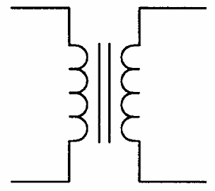
What is the Graphical Symbol of Transformer? Transformer Symbol

The Graphical Symbol of Transformer is:

Which character or alphabet indicates a Transformer?

Transformer is indicated by the alphabet T

What is the Work of a Transformer?

The main function of a Transformer is increase or decrease AC voltage.

What is the Unit of Transformer?

The Unit of Transformer is Volt Ampere.

Step Down Transformer

When the voltage of the input of the secondary winding or coil is lower than the input given in the first winding, it is called step down transformer.

Step Up Transformer

When the voltage of the output of the secondary winding or coil is higher that the input given in the first winding, it is called step up transformer.

How to Check Transformer?

Resistance should be checked when primary and secondary coils are checked separately. If only 1 is displayed, it means that the coil is OPEN. If beep sound or reading is received in one wire each of primary and secondary coil, it means the transformer is short.


// ]]>

Related Posts:

Types of Diode in Mobile Cell Phone and Their Function

$
0
0

A solid state device with two electrodes which passes only the electric current of a particular polarity from one side in called diode. Solid state diode is generally made of germanium or silicon semiconductor. This is used for rectification and switching.

Several types of diodes are used in electronic instruments and gadgets. Chip diodes are used in mobile cell phones and other telecommunication devices. These are surface mount devices (SMD). Surface mount devices are soldered with special soldering technique called SMT.

Important facts about diodes:

  1. Indicating Character of Diode : D or V
  2. Function: Making AC to DC (Converting) and Do the Switching.

P-N Junction Diode

Diode Symbol

Diode Symbol

Components made with the combination of P-Type and N-Type semiconductors are called diode. They are also called P-N Junction Diode.

P-type part of the diode is called anode and N-type is called cathode. The point where both these sides combine is called depletion layer because in this section, the electrons and holes remain neutral and do not attract each other. Due to this depletion layer, the electrons from either side cannot unite.


// ]]>

How Does Diode Work?

The required voltage to activate a diode is called diode biasing. Biasing is of two types –

  1. Forward Biasing; and
  2. Reverse Biasing

Forward Biasing

When positive supply is given on the anode and negative supply is given to the cathode, it is called forward biasing. This creates HOLE in anode (P-area) of diode and pressure is created on cathode (N-area) because equal charges repel each other. As the pressure continues to increase, resistance of the depletion layer (Junction) decreases to zero and the current flow starts.

Reverse Biasing

Supply of negative to anode (P) terminal and positive to cathode (N) terminal is called reverse biasing. As a result, the HOLES of anode of the diode attract the electrons of battery and the positive terminal of the battery attracts the electrons of the cathode and the resistance of depletion layer goes on increasing and stops the flow of current.

What is Rectification?

Mostly AC is used for electrical energy but in some cases DC has to be used. The process of conversion of AC to DC is called rectification.

What is Signal Diode?

This type of diode is used for detecting signals. These diodes are made of glass. A red ring on the terminal marks its cathode. These diodes are available in following numbers – IN4 148, IN34, OA79 etc. SMD signal diode is also available in black color.

What is Zener Diode?

Zener Diode

Zener Diode

This is a special type of diode made with silicon which is used to keep the output supply stable. Zener diodes are used to stabilize voltage. Zener diode is represented by “Z”. Zener diode is recognized by its “Zener Volt” like 3.0VZ, 3.9VZ, 5.1VZ, 6.2VZ etc.

What is Varacter Diode?

This is a variable capacitance diode which functions on the principle of variable capacitor. These diodes function within a defined range of capacity. Varacter diodes are available in the values ranging from 1 to 500 pf and 10 to 100 V. These are used in the signal transmission circuits.

What is Tunnel Diode?

These diodes are used for processing the properties of negative resistance and are used for switching at microwave frequency level.

What is LED or Light Emitting Diode?

LED Diode

LED Diode

These are diodes that produce light after receiving forward biasing. They are used to en light the display or keypad in mobile cell phone.


// ]]>

Related Posts:

Surface Mount Transistor in Mobile Cell Phone and Their Function

$
0
0

Surface Mount Transistor or SMT Transistor is an SMD electronic component made up of semiconductor material like silicon or germanium. There are 2 types of Surface Mount Transistors:

  1. NPN Type
  2. PNP Type

There are three terminals of a transistor:

  1. Ammeter (E) – Flows current on receipt of forward bias. Electrons are emitted in NPN transistors whereas PNP transistors emit ‘holes’.
  2. Collector (C) – The terminal of the transistor which receives the emitted electrons or holes. Collector always works or reverse bias mode.
  3. Base (B) – The layer between ammeter and collector is called base. Base displays the property of showing low resistance in ammeter junction forward bias and high in collector junction reverse bias.

Facts about Transistor:

  1. Indicating Character: Q or V, TR
  2. Function: Switching, Amplification, Regulating Voltage.
  3. Unit: Transistors are identified according to the code.

Digital Transistor

In digital transistor, resistance in built in the base and ammeter. This transistor is also called RET (Resistance Equipped Transistor). This type of transistor is used in mobile phones for reducing the current consumption.

Field Effect Transistor (FET)

Surface Mount Transistor

Surface Mount Transistor

This type of transistor is controlled by voltage instead of current. Flow of working current through a semiconductor channel is switched and regulated by the effect of electrical charge in the area near channel which is called gate. This is called unipolar transistor. FET can be P-Channel type or N-Channel Type.

Metal Oxide Semiconductor (MOSFET)

MOSFET is active semiconductor components. MOSFET has 3 terminals – source, drain and gate. There are 2 types of MOSFET:

  1. P-Channel MOSFET (PMOS)
  2. N-Channel MOSFET (NMOS)


// ]]>

Related Posts:


Integrated Circuit (IC)

$
0
0

Integrated Circuit or IC is an electronic component made up of combination of several transistors, diode, resistor, capacitors in a tiny semiconductor chip. Integrated Circuit Electronic Components or IC are of small size and very light weight. They produce excellent results at low power. Components used in an IC are not visible from outside. These are built in a semiconductor chip and cannot be removed. Capacitors of more than 30 PF value are not used in IC nor can inductors and transformers be mounted inside the chip of an IC. Thousands and millions of bi-polar transistors and CMOS (Complimentary Metal Oxide Semiconductor) FET are used in making an IC..

Types of Integrated Circuit (IC)

On the basis of external structure, ICs can be classified as follows:

  1. Single in-line pin package (SIPP).
  2. Dual in-line pin package (DIPP).
  3. Quard pin package.
  4. Pin Grid Array Package (PGA).
  5. Ball Grid Array Package (BGA).
  6. Leadless Chip Carrier (LCC) Package.


// ]]>

BGA IC – Ball Grid Array

IC without pins are used in mobile phones which are called Ball Grid Array (BGA). To count the number of pins in a BGA IC, there is a circular point sign on a corner upside, or there is a deep circular sign. Ball Grid Array is kept on the palm in a manner so that the circular sign faces the thumb downwards. Read: Counting Legs or Pins of an IC

Integrated Circuit

Integrated Circuit

Types of Integrated Circuit (IC) on Basis of Technology

There are two types of IC on the basis of technology:

  1. Linear IC – This type of IC works on analog signal where output signal varies according to the variable input signal.
  2. Digital IC – This type of IC works on digital signal. A defined output signal is received from a defined input signal. On the basis of electronic components used, the digital IC are of various types. Examples of Digital IC – CMOS (Complimentary Metal Oxide Semiconductor), DSP (Digital Signal Processor), DRAM (Dynamic Random Access Memory), ROM (Read Only Memory), PROM (Programmable Read Only Memory).


// ]]>

Related Posts:

Mobile Phone Parts

$
0
0

Mobile phone parts and components consist of several small, medium and large parts and components. Parts and components in most mobile cell phones are more or less the same including – Samsung, Nokia, Acer, Alcatel, Apple, Geonee, Asus, BenQ, Siemens, Bird, Blackberry, Blu, Celkon, Dell, Gigabyte, Haier, HT, Huawei, Micromax, LG, Motorola, iMobile, i-Mate, Panasonic, Philips, Spice, Sony, Sony Ericsson, Toshiba, ZTE Etc.

Mobile Phone Parts

Mobile Phone Parts


// ]]>

Mobile phone Parts and Components:

  1. Antenna – Antenna in a mobile cell phone is used to receive and transmit radio frequency. Antenna is inbuilt in the cabinet of the mobile phone. These are called inbuilt antenna.
  2. Battery– The battery is the only source of power supply to a mobile phone. Three types of battery (3.6V) are used in most mobile cell phones – (1) Nickel – Cadmium (Ni-CD) (2) Nickel Metal Hydride (Ni – MH) (3) Lithium – Ion (Li – Ion).
  3. Battery Charger – Several types of mobile phone charges are used recharge the battery of a mobile cell phone. These include normal mobile phone battery chargers, Travel Adaptor (TA), Cigar Lighter Adaptor (CLA) etc.
  4. Switch or Key Tip – These tiny switches are used for the key pad of mobile phones.
  5. Central Processing Unit (CPU) – The CPU is the control section of a mobile phone that controls all the function of the mobile phone. It does all the processing work of the phone.
  6. RAM (Random Access Memory) – RAM is an erasable memory where older data and information can be erased and new data and information can be stored.
  7. ROM (Read Only Memory) – A memory that can only be read. It cannot be erased. Programmable ROM (PROM) and Erasable ROM (EROM) are some other types of Rom Memory that can be erased.
  8. Visual Display – This part of the mobile phone generates light to display all information. Display of a mobile cell phone can be classified as follows – (1) LCD (Liquid Crystal Display), (2) VFD (Vacuum Fluorescent Display), (3) TFT (Thin Film Transistor Display).
  9. Antenna Switch – Part of a mobile phone that that does the function of receiving, transmitting and switching of different frequencies like GSM, DCS and PCS.
  10. IF IC – This IC is also called Hager IC, MJOLNER IC and RF IC. It performs the function of amplification of receiving signal, mixing and demodulation.
  11. VCO (Voltage Control Oscillator) – Controls frequency.
  12. Audio IC – The main function of this IC is to handle and control audio frequency and produce sound.
  13. UEM IC (Universal Energy Module) – It performs several functions like power supply, charging, audio processing, ringer vibrator etc.
  14. LED (Light Emitting Diode) – It is used to produce light on keyboard and display.
  15. RF Crystal – This is the main and very important crystal in any mobile phone. Crystals of mainly 13 MHz, 26 MHz, 19.2 MHz or 36.4 MHz are used in cell phones. Mobile phone becomes dead if this crystal is faulty.
  16. Ear Speaker – This speaker is mounted on the top side of the mobile phone. It helps to listen sound.
  17. Microphone – It converts voice signal to electric signal or tone signal during transmission. This signal is then sent to the Audio IC.
  18. Vibrator Motor – Provides vibration alert during incoming calls or messages in silent mode or when the option is On.
  19. SIM card – SIM stands for Subscriber Identity Module. It is used in GSM Mobile phones. There is a micro chip in this card in which all data and information related to the USER and the Mobile Phone is stored. Without a SIM Card, a GSM mobile phone is of no good use.
  20. SIM card Socket – Holds the SIM card and acts like a SIM reader or SIM writer.
  21. Memory Card – External memory storage card used to store data such as photos, videos, audio etc. SD card, Mini SD Card and Micro SD cards are used as external memory in mobile phones.
  22. External Antenna Socket – External antenna can be connected with the help of accessories in this socket. This helps to increase the range of internal antenna.
  23. RETU IC – This module performs several important functions for the mobile phone.
  24. TAHVO IC – This module also performs several important functions in a mobile phone.
  25. OMAP Module – Performs the function of processing application software and control UI software.
  26. Hands free Connector – Helps to carry on conversation on a mobile phone without holding it in hand using head phone.
  27. Flash IC – This memory inside a mobile phone is used to store programs and non volatile data.
  28. RAP 3G IC – This IC has been used as core with non Flash and SD RAM memory module in modem section. RAP3G module works as cellular protocol with WCDMA and GSM.
  29. USB Connector – This connector is used to download data and for charging the mobile phone.,
  30. Joy Stick – Used to ease the function of the user. User can control the operation of a mobile phone by setting the functions of joystick.
  31. Software Connector Parts – Used for flashing of mobile phone. Mobile phone may be connected to a Computer through this connector to solve software related problems.
  32. Connector Tip – Used to interface speaker, ringer, vibrator and antenna.
  33. Testing Points – Output of various types of signals are checked from these tips with the help of CRO.
  34. LTR – This regulator part is used to regulate the voltage in a mobile phone.
  35. AVILMA IC, BETTY IC, UIM Card – Few other parts inside a mobile phone.


// ]]>

Related Posts:

Counting Legs or Pins of IC

$
0
0

Any mobile phone PCB has several IC or Integrated Circuit. These are SMD or Surface Mount Electronic Components. Before understanding how to count legs or pins of any IC, let us learn about IC. What is an IC?...

The post Counting Legs or Pins of IC appeared first on Mobile Phone Repairing.

How to Check Parts of a Mobile Phone for Fault

Types of Filters in Mobile Cell Phone and Their Function

Viewing all 22 articles
Browse latest View live